Thin-film interference is a natural phenomenon in which
light waves reflected by the upper and lower boundaries of a
thin film interfere with one another, either enhancing or reducing the reflected light. When the thickness of the film is an odd multiple of one quarter-
wavelength of the light on it, the reflected waves from both surfaces interfere to cancel each other. Since the wave cannot be reflected, it is completely transmitted instead. When the thickness is a multiple of a half-wavelength of the light, the two reflected waves reinforce each other, increasing the reflection and reducing the transmission. Thus when white light, which consists of a range of wavelengths, is incident on the film, certain wavelengths (colors) are intensified while others are
attenuated. Thin-film interference explains the multiple colors seen in light reflected from soap bubbles and oil films on water. It also is the mechanism behind the action of
antireflection coatings used on glasses and camera lenses.

Demonstration of the optical path length difference for light reflected from the upper and lower boundaries of a thin film.
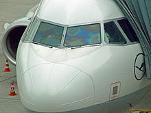
Thin-film interference caused by
ITOdefrosting coating on an
Airbus cockpit window.
A
thin film is a layer of material with thickness in the sub-
nanometer to
micron range. As light strikes the surface of a film it is either transmitted or reflected at the upper surface. Light that is transmitted reaches the bottom surface and may once again be transmitted or reflected. The
Fresnel equations provide a quantitative description of how much of the light will be transmitted or reflected at an interface. The light reflected from the upper and lower surfaces will interfere. The degree of constructive or destructive
interference between the two light waves depends on the difference in their phase. This difference in turn depends on the thickness of the film layer, the refractive index of the film, and the angle of incidence of the original wave on the film. Additionally, a phase shift of 180° or

radians may be introduced upon reflection at a boundary depending on the refractive indices of the materials on either side of the boundary. This phase shift occurs if the refractive index of the medium the light is travelling through is less than the refractive index of the material it is striking. In other words, if

and the light is travelling from material 1 to material 2, then a phase shift occurs upon reflection. The pattern of light that results from this interference can appear either as light and dark bands or as colorful bands depending upon the source of the incident light.
Consider light incident on a thin film and reflected by both the upper and lower boundaries. The optical path difference (OPD) of the reflected light must be calculated in order to determine the condition for interference. Referring to the ray diagram above, the OPD between the two waves is the following:

Where,


Interference will be constructive if the optical path difference is equal to an integer multiple of the wavelength of light,

.

This condition may change after considering possible phase shifts that occur upon reflection.
Monochromatic source[edit]
Where incident light is
monochromatic in nature, interference patterns appear as light and dark bands. Light bands correspond to regions at which constructive interference is occurring between the reflected waves and dark bands correspond to destructive interference regions. As the thickness of the film varies from one location to another, the interference may change from constructive to destructive. A good example of this phenomenon, termed "
Newton's rings," demonstrates the interference pattern that results when light is reflected from a spherical surface adjacent to a flat surface. Concentric rings are viewed when the surface is illuminated with monochromatic light.
Broadband source[edit]
If the incident light is broadband, or white, such as light from the sun, interference patterns appear as colorful bands. Different wavelengths of light create constructive interference for different film thicknesses. Different regions of the film appear in different colors depending on the local film thickness.
Phase interaction[edit]
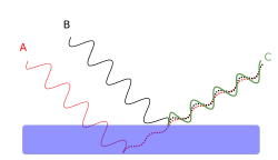
Constructive phase interaction

Destructive phase interaction
This section provides a simplified explanation of the phase relationship responsible for most of this phenomenon. The figures show two incident light beams (A and B). Each beam produces a reflected beam (dashed). The reflections of interest are beam A’s reflection off of the lower surface and beam B’s reflection off of the upper surface. These reflected beams combine to produce a resultant beam (C). If the reflected beams are in phase (as in the first figure) the resultant beam is relatively strong. If, on the other hand, the reflected beams have opposite phase, the resulting beam is attenuated (as in the second figure).
The phase relationship of the two reflected beams depends on the relationship between the wavelength of beam A in the film, and the film's thickness. If the total distance beam A travels in the film is an integer multiple of the wavelength of the beam in the film, then the two reflected beams are in phase and constructively interfere (as depicted in the first figure). If the distance traveled by beam A is an odd integer multiple of the half wavelength of light in the film, the beams destructively interfere (as in the second figure). Thus, the film shown in these figures reflects more strongly at the wavelength of the light beam in the first figure, and less strongly at that of the beam in the second figure.
Examples[edit]
The type of interference that occurs when light is reflected from a thin film is dependent upon the wavelength and angle of the incident light, the thickness of the film, the refractive indices of the material on either side of the film, and the index of the film medium. Various possible film configurations and the related equations are explained in more detail in the examples below.
Soap bubble[edit]

Thin film interference in a soap bubble. Color varies with film thickness.
Light incident on a soap film in air
In the case of a
soap bubble, light travels through air and strikes a soap film. The air has a refractive index of 1 (

) and the film has an index that is larger than 1 (

). The reflection that occurs at the upper boundary of the film (the air-film boundary) will introduce a 180° phase shift in the reflected wave because the refractive index of the air is less than the index of the film (

). Light that is transmitted at the upper air-film interface will continue to the lower film-air interface where it can be reflected or transmitted. The reflection that occurs at this boundary will not change the phase of the reflected wave because

. The condition for interference for a soap bubble is the following:
 for constructive interference of reflected light
 for destructive interference of reflected light
Where

is the film thickness,

is the refractive index of the film,

is the angle of incidence of the wave on the lower boundary,

is an integer, and
is the wavelength of light.
Oil film[edit]
Light incident on an oil film on water
In the case of a thin oil film, a layer of oil sits on top of a layer of water. The oil may have an index of refraction near 1.5 and the water has an index of 1.33. As in the case of the soap bubble, the materials on either side of the oil film (air and water) both have refractive indices that are less than the index of the film.

. There will be a phase shift upon reflection from the upper boundary because

but no shift upon reflection from the lower boundary because

. The equations for interference will be the same.
 for constructive interference of reflected light
 for destructive interference of reflected light
Anti-reflection coatings[edit]
Light incident on an anti-reflection coating on glass
An anti-reflection coating eliminates reflected light and maximizes transmitted light in an optical system. A film is designed such that reflected light produces destructive interference and transmitted light produces constructive interference for a given wavelength of light. In the simplest implementation of such a coating, the film is created so that its optical thickness

is a quarter-wavelength of the incident light and its refractive index is greater than the index of air and less than the index of glass.


A 180° phase shift will be induced upon reflection at both the top and bottom interfaces of the film because

and

. The equations for interference of the reflected light are:
 for constructive interference
 for destructive interference
If the optical thickness
is equal to a quarter-wavelength of the incident light and if the light strikes the film at normal incidence

, the reflected waves will be completely out of phase and will destructively interfere. Further reduction in reflection is possible by adding more layers, each designed to match a specific wavelength of light.
Interference of transmitted light is completely constructive for these films.
In nature[edit]

The blue wing patches of the
Aglais io butterfly are due to thin-film interference.
[1]

The gloss of
buttercup flowers is due to thin-film interference.
Structural coloration due to thin-film layers is common in the natural world. The wings of many insects act as thin films because of their minimal thickness. This is clearly visible in the wings of many flies and wasps. In butterflies, the thin-film optics are visible when the wing itself is not covered by pigmented wing scales, which is the case in the blue wing spots of the
Aglais io butterfly.
[1] The glossy appearance of buttercup flowers is also due to a thin film
[2] as well as the shiny breast feathers of the
bird of paradise.
[3]
Applications[edit]
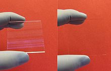
An antireflection coated piece of glass
(right) compared to an ordinary uncoated glass
(left)
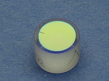
Thin-film coatings are used in
dielectric mirrors to provide near-total reflection of light over a limited range of wavelengths.
Thin films are used commercially in anti-reflection coatings, mirrors, and optical filters. They can be engineered to control the amount of light reflected or transmitted at a surface for a given wavelength. A
Fabry–Pérot etalon takes advantage of thin film interference to selectively choose which wavelengths of light are allowed to transmit through the device. These films are created through deposition processes in which material is added to a substrate in a controlled manner. Methods include
chemical vapor deposition and various
physical vapor deposition techniques.
Thin films are also found in nature. Many animals have a layer of tissue behind the retina, the
Tapetum lucidum, that aids in light collecting. The effects of thin-film interference can also be seen in oil slicks and soap bubbles. The
reflectance spectrum of a thin-film features distinct oscillations and the extrema of the spectrum can be used to calculate the thickness of the thin-film.
[1]
Ellipsometry is a technique that is often used to measure properties of thin films. In a typical ellipsometry experiment polarized light is reflected off a film surface and is measured by a detector. The complex reflectance ratio,

, of the system is measured. A model analysis in then conducted in which this information is used to determine film layer thicknesses and refractive indices.
Dual polarisation interferometry is an emerging technique for measuring refractive index and thickness of molecular scale thin films and how these change when stimulated.
History[edit]

Tempering colors are produced when steel is heated and a thin film of iron oxide forms on the surface. The color indicates the temperature the steel reached, which made this one of the earliest practical uses of thin-film interference.
Iridescence caused by thin-film interference is a commonly observed phenomenon in nature, being found in a variety of plants and animals. One of the first known studies of this phenomenon was conducted by
Robert Hooke in 1665. In
Micrographia, Hooke postulated that the iridescence in
peacock feathers was caused by thin, alternating layers of plate and air. In 1704,
Isaac Newton stated in his book,
Opticks, that the iridescence in a peacock feather was due to the fact that the transparent layers in the feather were so thin.
[4] In 1801,
Thomas Young provided the first explanation of constructive and destructive interference. Young's contribution went largely unnoticed until the work of
Augustin Fresnel. In 1816, Fresnel helped to establish the wave theory of light.
[5]However, very little explanation could be made of the iridescence until the 1870s, when
James Maxwell and
Heinrich Hertz helped to explain
the electromagnetic nature of light.
[4] After the invention of the
Fabry–Perot interferometer, in 1899, the mechanisms of thin-film interference could be demonstrated on a larger scale.
[5]
In much of the early work, scientists tried to explain iridescence, in animals like peacocks and
scarab beetles, as some form of surface color, such as a dye or pigment that might alter the light when reflected from different angles. In 1919,
Lord Rayleigh proposed that the bright, changing colors were not caused by dyes or pigments, but by microscopic structures, which he termed "
structural colors."
[4] In 1923, C. W. Mason noted that the barbules in the peacock feather were made from very thin layers. Some of these layers were colored while others were transparent. He noticed that pressing the barbule would shift the color toward the blue, while swelling it with a chemical would shift it toward the red. He also found that bleaching the pigments from the feathers did not remove the iridescence. This helped to dispel the surface color theory and reinforce the structural color theory.
[6]
In 1925,
Ernest Merritt, in his paper
A Spectrophotometric Study of Certain Cases of Structural Color, first described the process of thin-film interference as an explanation for the iridescence. The first examination of iridescent feathers by an
electron microscope occurred in 1939, revealing complex thin-film structures, while an examination of the
morpho butterfly, in 1942, revealed an extremely tiny array of thin-film structures on the nanometer scale.
[4]
The first production of thin-film coatings occurred quite by accident. In 1817,
Joseph Fraunhofer discovered that, by tarnishing
glass with
nitric acid, he could reduce the reflections on the surface. In 1819, after watching a layer of alcohol evaporate from a sheet of glass, Fraunhofer noted that colors appeared just before the liquid evaporated completely, deducing that any thin film of transparent material will produce colors.
[5]
See also[edit]
References[edit]
- ^ Jump up to: a b c Stavenga, D. G. (2014). "Thin Film and Multilayer Optics Cause Structural Colors of Many Insects and Birds" (PDF). Materials Today: Proceedings. 1: 109. doi:10.1016/j.matpr.2014.09.007.
- Jump up ^ Van Der Kooi, C. J.; Wilts, B. D.; Leertouwer, H. L.; Staal, M.; Elzenga, J. T. M.; Stavenga, D. G. (2014). "Iridescent flowers? Contribution of surface structures to optical signaling" (PDF). New Phytologist. 203 (2): 667. doi:10.1111/nph.12808. PMID 24713039.
- Jump up ^ Stavenga, D. G.; Leertouwer, H. L.; Marshall, N. J.; Osorio, D. (2010). "Dramatic colour changes in a bird of paradise caused by uniquely structured breast feather barbules". Proceedings of the Royal Society B: Biological Sciences. 278 (1715): 2098. doi:10.1098/rspb.2010.2293.
- ^ Jump up to: a b c d Structural colors in the realm of nature By Shūichi Kinoshita – World Scientific Publishing 2008 pages 3–6
- ^ Jump up to: a b c d Thin-film optical filters By Hugh Angus Macleod – Institute of Physics Publishing 2001 Pages 1–4
- Jump up ^ Structural colors in the realm of nature By Shūichi Kinoshita - World Scientific Publishing 2008 Page 165-167
Further reading[edit]
- Fowles, Grant R. (1989), "Multiple-Beam Interference", Introduction to Modern Optics, Dover
- Greivenkamp, John (1995), "Interference", Handbook of Optics, McGraw–Hill
- Hecht, Eugene (2002), "Interference", Optics, Addison Wesley
- Knittl, Zdeněk (1976), Optics of Thin Films; An Optical Multilayer Theory, Wiley
- D.G. Stavenga, Thin film and multilayer optics cause structural colors of many insects and birds Materials today: Proceedings, 1S, 109 – 121 (2014).


_2.jpg)


